Step Eleven: Installing a Galaga to Jamma Harness
Board swapping is simply a means of changing games by installing a different game circuit board in a cabinet and using its existing power supply, monitor and controls to play the game. The key to determining if a board is compatible with your game is to confirm that the board you want to install uses the same components of your game. Let’s examine these components one by one:
Sometime around 1986, the arcade manufacturers decided that using different pinouts for each game was a bit of pain and that if a standard was developed, games could more easily be converted to other games. This standard pinout that was developed is know as JAMMA (which stands for Japanese Arcade Machine Manufacturers Association).
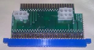
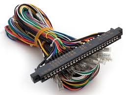
With the advent of JAMMA swapping game boards between cabinets became much easier, since the boards used the same pinouts the primary issue to contend with was/is the orientation of the monitor and input controls.Prior to JAMMA there were a few pinout classes that were used by multiple games, allowing some board swapping to be feasible. Remember just because these games have compatible pinouts, you’d still need to check the monitor orientation and control setup before being sure you could play one game in another’s game cabinet. In recent history, a Galaga to JAMMA board like below has been manufactured to make updating your original Galaga game even that much easier:
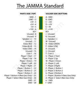
JAMMA Pinout
If a game board has the same pinout as another game that swapping boards is just a matter of installing the game board in the existing cabinet, since it uses the same pins.
Unfortunately, most classic games (games made before 1985) use unique pinouts and can’t be swapped easily with one another.
Understanding the JAMMA Pinout Chart:
Solder Side – The bottom side of the pcb. The side where the soldered connections of parts are exposed to view. Few, if any, parts are located on the solder side.
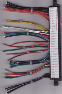
Parts (Component) Side – The top side of the pcb. The side where the parts are located. The parts side can be viewed in the pcb photo above.
N/C – No connection.
Key Slot – A keyed slot which aligns with a leave-out in the pinout section of the pcb.
This safety feature is provided to assure that the Power Section seats at the correct end of the pinout section. If the edge connector is reversed, and the Power Section is seated at the opposite or incorrect end, irreparable damaged can occur to the pcb.
If the key has been removed from the edge connector, then mark the connector as to the “Parts Side” to help assure correct seating.
Power Section – Pins A-F, 1-6
Video Section – Pins N, P, 13-15
Coin Section – Pins J, K, T, 8, 9, 16
Controller (Joystick) Section – Pins V-Y, 18-21
Pushbutton Switch Section – Pins Z-b, 22-24
Ground (Common) Section – Pins e, f, 27, 28 (incorrectly often called Ground, correct term is Common)
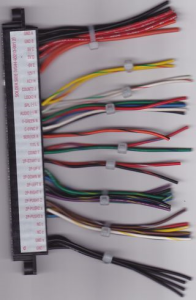
Photos of the JAMMA Edge Connector:
To Buy a Jamma Harness
Warning – Wire colors change from one maker’s harness to another maker’s harness. So, when attaching wiring to components, rely on the wire’s edge connector position and number, not on the wire’s color. This is particulary important when connecting the harness to the power supply. While black is usually Common, red is usually +5VDC, and orange is usually +12VDC, these standard wire colors may not always be used.If you accidentally connect the +5VDC wire to the +12VDC power supply terminal, you could ruin your printed circuit board.
Converting Your Pacman To Jamma
In order to convert your original Pacman or Ms. Pacman to Jamma you will first need a Pac to Jamma Adapter.
You will also need a new 15 amp Power supply and a Jamma wiring harness.
Once you have these items, then you will need to follow the instructions given with your adapter, but its really as simple as wiring the jamma harness pinout wires to the +5, +12,-5, power, coin door, sound, monitor signals & sync, and finally grounds of the Power supply. Then plug the Jamma wiring harness into the top of the Galaga to jamma adapter with the original board plugged into the bottom connector of the adapter. Very simple to do and you’ll save a lot of time and future trouble with your Galaga game. Plus you can swap out other games that are compatible with the monitor.
TO add a 15 amp power supply and further info on this topic Go to the Installing a new 15 amp power supply post.
more info on Installing 15Amp Power supply
Return Home

What voltage is the coin slot and which contact goes to positive side ,normally open or Normally close .
Connect pinout K to the Normally Open (NO) and the ground wired to the COM leg of the coin slot switch. Voltage is going thru the K wire will be correct for the coin slot. Dont remember if its +5 or +12 but it doesn’t matter just connect that K wire from the galaga pinout to the No of the coin slot